You need to create a long, continuous line of light, but you just string multiple strips together end-to-end. The result is a disaster: the strip is bright at the beginning but dim and discolored at the end, and the connection points are getting hot.
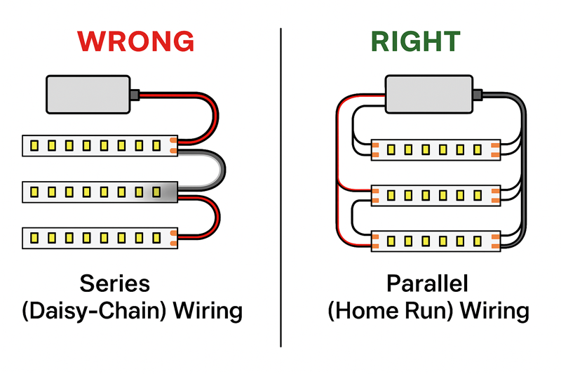
To connect multiple LED strips, you must wire them in parallel to a single, adequately sized power supply. Never connect them in a long series (daisy-chain) beyond the recommended maximum length, as this will cause severe voltage drop and potential failure.
I once got a frantic call from an electrical contractor, a guy we’ll call "Pro-level Tom," who was installing cove lighting in a massive hotel lobby. The perimeter was over 100 feet. His crew had connected six of our 16.4-foot reels in one long, continuous chain, powered from a single end. He said, "Jermey, the first two reels look great, the third is a little yellow, and the last three are a dim orange. Your product is inconsistent!" I had him send me a video, and I knew instantly what the problem was. It wasn’t the product; it was physics. I had to explain voltage drop and why a 100-foot-long, low-voltage circuit was doomed to fail. We had to rework the installation into a parallel layout with multiple power feeds. It was a tough lesson for him, but it’s one every professional needs to learn: when you connect multiple strips, the wiring strategy is everything.
Why Can’t You Just Daisy-Chain Multiple Strips End-to-End?
It seems so easy—just plug one strip into the next. But this simple approach is causing massive headaches, with inconsistent brightness and color that makes your professional work look amateurish. You’re fighting a losing battle against physics.
Daisy-chaining multiple full reels in series overloads the copper traces on the first strip. This causes a severe voltage drop, leading to dimming and color shifts, and creates excess heat at the connection points, which is a major fire hazard.

Think of the flexible circuit board (PCB) of an LED strip like a water pipe. The power supply is the pump, and the electricity is the water. The first reel is a pipe of a certain diameter. It’s designed to carry enough "water" for its own LEDs. When you connect a second reel to its end, you are now forcing the "pipe" of that first reel to carry water for itself and for the second reel. Add a third, and it gets even worse. The tiny copper traces on that first strip simply can’t handle the load. The pressure (voltage) drops, and the flow (current) can’t get to the end. The strip itself becomes a bottleneck. This isn’t a defect; it’s a fundamental design limitation. Respecting that limit is the key to a successful multi-strip installation.
Understanding the Electrical Bottleneck
Every professional installer needs to understand that LED strips are not extension cords. The thin copper pathways on the flexible PCB are carefully engineered to power only the LEDs on that specific length of strip—typically 5 meters (16.4 feet). Exceeding this length by daisy-chaining creates a cascade of problems. The initial strips in the chain are forced to carry more current than they were designed for, leading to heat generation, which can degrade the LEDs and the adhesive. Further down the line, the voltage drops so significantly that the LEDs don’t receive enough power to operate at their specified brightness and color temperature. This is why a parallel wiring plan is not just a "best practice"; it is the only professionally acceptable method for long runs.
| Problem | Technical Cause | Consequence for the Installation | How Parallel Wiring1 Solves It |
|---|---|---|---|
| Dimming | Voltage Drop2. The resistance of the long copper trace causes the voltage to decrease along the length of the strip. 24V at the start might become 20V at the end. | The LEDs at the end of the run are severely underpowered, resulting in a noticeable and unprofessional fade in brightness. | Each parallel strip gets its own direct wire "feed" from the power supply, ensuring every strip in the installation receives the full, correct voltage. |
| Color Shift | Voltage Drop. As voltage drops, the blue LEDs (which require slightly more voltage to activate fully) dim more than the red and green LEDs. | White light becomes warmer and more yellow or reddish towards the end of the run. This is extremely obvious in architectural coves. | By providing full voltage to all strips, the balance of red, green, and blue light output is maintained, ensuring consistent color from start to finish. |
| Heat & Fire Risk3 | Excessive Current. The first strip in the daisy-chain is forced to carry the current for all subsequent strips, exceeding its rated amperage. | The copper traces and solder joints can overheat, causing the PCB to delaminate, melting the plastic housing, and creating a potential fire hazard. This is a serious safety concern. | In a parallel circuit, each wire run and each strip only has to carry its own load. Nothing is ever overloaded, eliminating the risk of overheating. |
| Inconsistent Lifespan | LED Overdriving/Underdriving4. The first LEDs may be slightly overdriven by current imbalances, while the last LEDs are underdriven. | The first section of the strip may fail prematurely due to stress, while the last section may outlive it but will never have performed correctly. | Every LED in the system operates under its designed electrical parameters, leading to a consistent and predictable lifespan across the entire installation. |
What is the Correct "Parallel Wiring" Method?
You know daisy-chaining is wrong, but you’re not sure about the correct way to wire multiple strips to a single power supply. You need a clear, repeatable strategy that works for any large project.
Create "parallel runs" or "home runs." This means running a separate pair of wires from your power supply’s output terminals directly to the start of each individual LED strip section. All strips are connected directly to the power source, not to each other.

I was helping a contractor, Tom, design the lighting for a long hallway in an office building. He wanted a continuous 50-foot run of light. We used three 16.4-foot reels. Instead of placing the power supply at one end, we installed it in a utility closet in the middle of the hallway. From the power supply’s terminal block, we ran one set of wires through the ceiling to the start of the first strip, a second set of wires to the start of the second strip, and a third set of wires to the start of the third strip. All three strips were powered independently from a central point. When he turned it on, the 50-foot line of light was perfectly uniform. Not a flicker of dimming or color shift. Tom said, "That’s how we’ll do it from now on." It’s a simple concept that guarantees professional results.
The Blueprint for Parallel Connections
Executing a parallel wiring plan is a systematic process. It requires a bit more planning and more wire than a simple series connection, but it is the foundation of a reliable, large-scale LED strip installation5. This is the method used in all high-end architectural, commercial, and hospitality projects. It ensures that every foot of the LED strip you install performs exactly as it was designed to. Mastering this technique is a non-negotiable skill for any serious lighting professional.
| Step | Action | Tools & Materials Needed | Jermey’s Pro Tip (Your Expertise) |
|---|---|---|---|
| 1. Centralize the Power Supply | Plan the installation by placing your power supply6 in a central, accessible location (like a utility closet, above the ceiling, or inside a cabinet). | LED Power Supply (Driver), Drill, Screws. | For very large projects, you may use multiple smaller power supplies instead of one giant one. This can simplify wiring and provide redundancy. Always ensure the location has adequate ventilation to keep the power supply cool. |
| 2. Calculate Total Power | Calculate the total wattage for ALL strips you plan to connect to the single power supply. Add the 20% safety margin to get your minimum required driver wattage. | Calculator, LED Strip Spec Sheet. | This is critical. If you have three 16.4ft reels of 4.5W/ft strip, the total is (3 16.4 4.5) * 1.2 = 265.7W. You must use a power supply rated for 300W or more. |
| 3. Run Your "Home Run" Wires | From the power supply’s output terminals (+ and -), run a separate pair of low-voltage wires to the physical starting point of each LED strip section. Label your wires! | Low-Voltage Wire (e.g., 18AWG CL2/CL3 in-wall rated), Wire Strippers, Label Maker or Tape. | Choose the right wire gauge! For long wire runs (over 20-30 feet), you must use a thicker gauge wire (like 16AWG or 14AWG) to prevent voltage drop in the wire itself. Use an online voltage drop calculator7 to be sure. |
| 4. Make the Connections | At the power supply, connect all positive (+) wires together and all negative (-) wires together at the driver’s output terminals. At the strip end, connect each wire pair to its corresponding LED strip using soldering (best) or a high-quality solderless connector. | Soldering Iron & Solder OR Solderless Connectors, Heat-Shrink Tubing, Screwdriver. | Use a multi-port terminal block (like a Wago lever nut or a bus bar) at the power supply for a cleaner, more secure connection when you have many wires. This is much better than trying to twist 3-4 wires into one terminal. |
How Do You Create a Seamless Physical Connection Between Strips?
You’ve wired your strips in parallel, but now you need to link them physically to create a continuous line of light with no dark spots. You need to turn a corner or bridge a gap. How do you do it without compromising the connection?
For straight-line extensions, butt the two strips end-to-end inside an aluminum channel and solder a small jumper wire between the pads. For corners, use specialized L-shaped solderless connectors or solder flexible wires between the strips.
An architect I work with is obsessed with clean lines of light. No gaps, no shadows. We were doing an under-cabinet installation where the run was interrupted by a range hood. We needed to bridge a 3-foot gap. The installer’s first instinct was to just use a long, ugly solderless connector cable. I showed him a better way. We cut the strips on both sides of the hood. Then, we drilled a small hole at the back of the cabinets and ran a thin, flexible two-conductor wire behind the hood, soldering it neatly to the copper pads on each strip end. When installed in the channel with a diffused cover, the light was perfectly continuous. There was no visible break. That attention to detail is what makes an installation look truly custom and high-end.
Techniques for Flawless Transitions
Achieving a continuous, seamless look when joining multiple strips is the final step in a professional installation. This is where craftsmanship comes into play. The goal is to make the connection points, corners, and jumps as invisible as possible. While parallel wiring handles the electrical load, these techniques handle the physical and aesthetic requirements of the job. Choosing the right method depends on whether you are making a simple straight extension, a sharp 90-degree corner, or bridging a larger gap in your run.
| Connection Type | Best Method | Why It Works | Jermey’s Installation Tip |
|---|---|---|---|
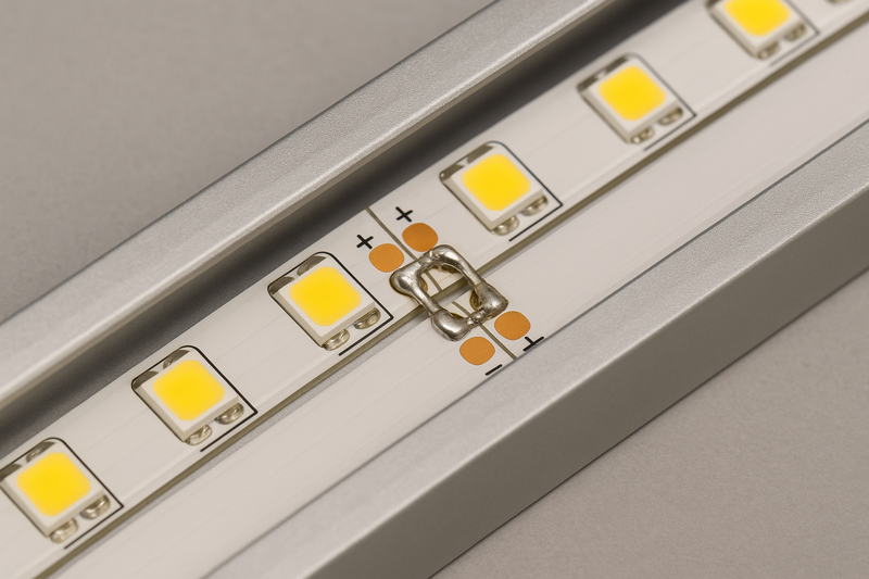
| Straight-Line Extension | Soldered Jumper Wires8. Cut short pieces of wire (about 1-2 inches) and solder them directly to the corresponding copper pads (+ to +, – to -) of the two strips. | Provides the most reliable and lowest-profile connection. Inside a channel with a diffuser, the connection is completely invisible and adds virtually no resistance. | After soldering, place a small piece of heat-shrink tubing over the joint before you slide it into the channel. This provides insulation and strain relief, making the connection much more robust. |
| 90-Degree Corner9 | Soldered Wire Jumpers. Solder 3-4 inches of flexible wire between the two strips, allowing you to create a clean, sharp corner turn. | This is the most reliable method for corners. It allows for flexibility in positioning and creates a solid electrical bond that won’t fail. | Cut the strips so the soldered joint is right at the corner. This minimizes any potential dark spots. Use different colored wires for + and – to avoid polarity mistakes. |
| 90-Degree Corner (Solderless) | L-Shaped Solderless Connectors10. These are rigid, pre-formed L-shaped connectors that clip onto the ends of two strips to create a 90-degree turn. | Very fast and easy solution for making corners without any tools or soldering skill. Good for DIY or rapid installations. | Buy high-quality ones! Cheaper versions can be unreliable. Ensure the connector is fully seated and clamped shut. This method is bulkier than soldering and may not fit in very slim aluminum channels. |
| Bridging a Gap (e.g., around a cabinet) | Custom-Length Wire Jumper11. Cut a length of low-voltage wire to the exact size of the gap you need to cross, and solder it to the ends of the two LED strips. | This gives you a fully custom, professional solution for navigating obstacles. The connection is permanent and reliable. | Plan your cuts carefully. Remember to account for the wire in your overall length calculations if it’s a long run. For a clean look, you can hide this jumper wire behind a cabinet frame or run it through the wall. |
Conclusion
Connecting multiple LED strips successfully is about strategy, not just brute force. Use parallel wiring to ensure electrical stability and choose the right connection method—preferably soldering—for a flawless, professional finish.
-
Exploring parallel wiring can help you implement the best practices for LED installations, ensuring safety and efficiency. ↩
-
Understanding voltage drop is crucial for ensuring optimal LED performance and avoiding dimming issues. ↩
-
Discover strategies to prevent overheating and fire hazards in LED setups, ensuring safety and reliability. ↩
-
Learn about overdriving and underdriving to maintain the longevity and performance of your LED installations. ↩
-
Explore this link to learn essential tips and techniques for a successful LED strip installation. ↩
-
Understanding power supply selection is crucial for optimal LED performance; this resource will guide you. ↩
-
A voltage drop calculator is vital for ensuring your LED strips function correctly over long distances. ↩
-
Explore the advantages of soldered jumper wires for reliable and low-profile connections in LED installations. ↩
-
Learn effective techniques for achieving sharp corners in LED strip lighting for a professional finish. ↩
-
Discover the ease and speed of using L-shaped solderless connectors for quick LED strip installations. ↩
-
Find out how to create custom-length wire jumpers for seamless transitions in your LED strip projects. ↩