You’ve created a stunning, perfectly straight run of light, but you get to a corner and everything falls apart. You’re left with an ugly loop, a dark spot, or a clumsy connection that ruins the entire high-end effect.
To master corners, cut the strip and use a soldered wire jumper for a clean 90-degree turn. For curves, use flexible strips designed for bending. In tight spaces, pre-wire components and use slim channels to manage the installation.
I once walked a job site for a luxury retail store with a very demanding architect. They had designed these beautiful floating shelves with integrated lighting that had to wrap around several inside and outside corners. The first electrical crew they hired had simply folded the LED strips at the corners, creating these ugly, bright loops. The architect was furious; it looked cheap and completely ruined the minimalist aesthetic. We came in and trained the new crew on how to properly cut, solder, and jump the corners. It took more time, but the result was a flawless, continuous line of light with no hotspots or shadows. That architect became one of my best clients. He said, "You understand that for us, the corners are where we judge the quality of the work." He was absolutely right.
How Do You Make a Perfect 90-Degree Corner?
You try to bend the strip around a sharp corner, but it either creates an ugly, bulging loop or you damage the circuit board. You need a method that is clean, reliable, and looks professionally integrated.
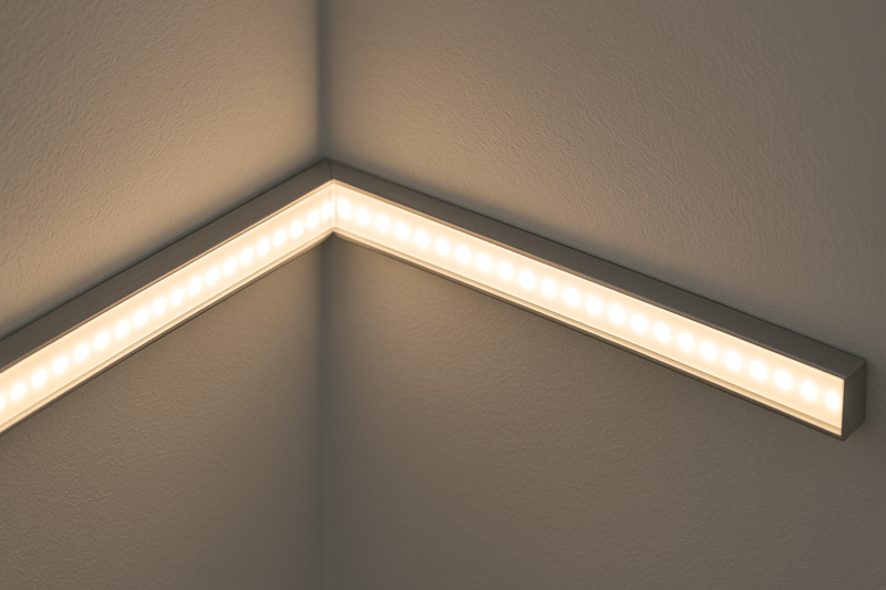
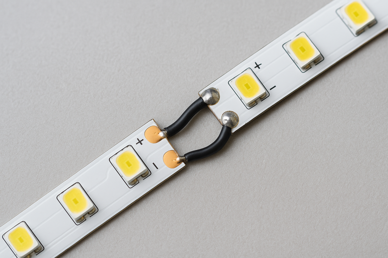
The best professional method is to cut the strip at the nearest cut mark, align the two pieces at a 90-degree angle, and bridge the connection by soldering a short, flexible wire jumper between the corresponding copper pads.
Early in my career, I saw installers use all sorts of tricks to avoid cutting the strip. The most common was the "fold and twist." They’d fold the strip back on itself to make the turn. While it kept the circuit intact, it created a hot spot of light and put immense stress on the solder joint of the nearest LED. A few months later, we’d get a call that a section of the strip was dead. Why? The stress from that fold had caused a micro-fracture in the circuit. That’s when I made it a rule for my teams: corners must be cut. Cutting and soldering a jumper wire takes 90 seconds, but it relieves all physical stress from the strip and creates a connection that will last as long as the LEDs themselves. It’s the difference between a temporary fix and a permanent, warrantable solution.
Mastering the Moment of Truth1
The corner is the moment of truth in any linear lighting installation. It’s the detail that separates a truly professional job from a hasty one. While it might seem faster to fold the strip, this shortcut introduces a point of failure and creates an unacceptable aesthetic flaw. A properly executed corner should be electrically sound, mechanically stable, and visually seamless. There are a few ways to achieve this, but soldering remains the gold standard for its reliability and low profile. For a professional like Tom, whose reputation is built on quality, taking the time to make corners correctly is a non-negotiable part of the job.
| Corner Technique | Description | Best For | Pros | Cons (And Why to Avoid for Pro Jobs) |
|---|---|---|---|---|
| The Fold & Twist (Not Recommended)2 | Bending the flexible strip back on itself to create a loop that turns the corner. | Absolutely no professional application. This is a common DIY shortcut that should be avoided. | None. There are no professional benefits to this method. It saves about one minute of time. | High Risk of Damage: Puts extreme stress on the circuit board and solder joints, leading to premature failure. Ugly Hotspot: Creates a bright, distracting loop of light that breaks the clean line. Unprofessional: Immediately signals a low-quality installation to any discerning client or architect. |
| Solderless L-Shaped Connectors3 | Rigid, pre-formed 90-degree plastic connectors that clamp onto the cut ends of two strips. | Quick-turnaround projects, temporary installations, or situations where soldering is not possible. | Fast and Easy: Requires no special tools or skills. Good for DIY: Very approachable for beginners. | Reliability Issues: The point of failure in many installations. Connection can loosen over time with vibration or temperature changes. Bulky: May not fit inside slim aluminum channels. Variable Quality: Cheap versions are extremely unreliable. |
| Soldered Wire Jumper4 (The Pro Method) | Cutting the strip and soldering a short, flexible 2-conductor wire to bridge the copper pads between the two sections. | All professional and permanent installations. This is the gold standard for high-end residential, architectural, and commercial projects. | Extremely Reliable: Creates a permanent, vibration-proof electrical and mechanical bond. Low Profile: Fits into any aluminum channel. Customizable: You can make the jumper wire longer to navigate complex angles or small gaps. | Requires Skill and Tools: Needs a soldering iron and basic soldering skills. Slightly More Time: Takes a few minutes longer per corner than a solderless connector. |
How Do You Handle Curved Surfaces?
You’re trying to install an LED strip around a curved reception desk or a circular ceiling cove. A standard strip will kink and buckle, refusing to follow the smooth contour and creating an unprofessional, segmented look.
For gentle curves, a standard strip can be carefully affixed by pressing down the inside edge first. For tighter curves, you must use a specialized "S-type" or "zigzag" flexible LED strip designed to bend horizontally.
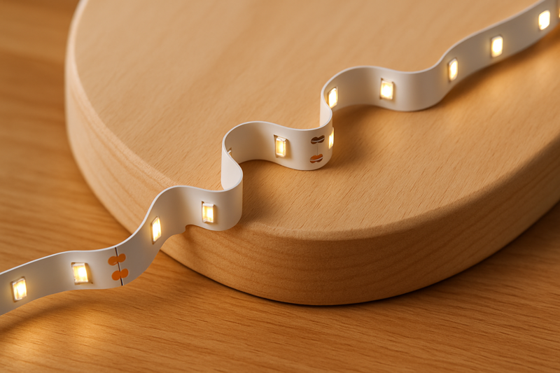
I was consulting on a project for a high-end bar. The centerpiece was this incredible, serpentine-shaped bar top, and the designer wanted a perfect halo of light under the countertop edge. The installers first tried to use one of our standard strips. On the gentle curves, it looked fine, but on the tighter turns, it was a mess. The strip would lift and crease. I had them switch to one of our S-type strips. The difference was night and day. The strip’s unique zigzag PCB allowed it to bend and flex like a ribbon, perfectly hugging every a single curve of the bar. It looked like the light was poured into place. The project manager, Tom’s counterpart, was amazed. He said, "Okay, having the right product for the job makes all the difference."
Choosing the Right Strip for the Bend
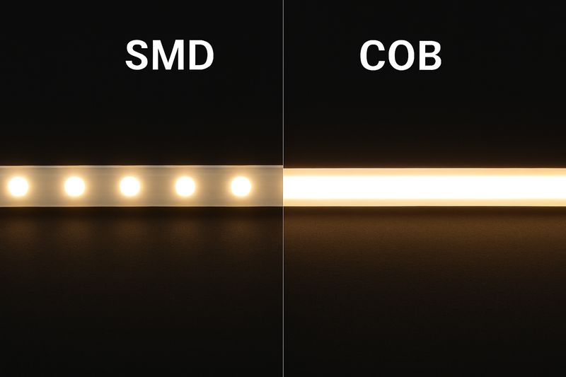
Not all curves are created equal. Understanding the physical limitations of a standard LED strip5 is crucial. A standard strip is essentially a thin, flat ribbon; it can bend vertically (like coiling into a reel) but resists bending horizontally. Forcing it to do so will damage the circuit. The solution is to use a product specifically designed for the task. This demonstrates a deeper level of product knowledge and ensures you can deliver on complex design specifications without compromising on quality or reliability.
| Curve Type | Recommended Strip Type | Installation Technique | Jermey’s Pro Tip |
|---|---|---|---|
| Gentle, Sweeping Curves (Radius > 24 inches / 60cm) | Standard LED Strip. Most high-quality strips have enough minor flexibility for large-radius curves. | Work from the inside out. Start by securing the inside edge of the strip along the curve. Then, gently press the rest of the strip’s width down. This prevents the outside edge from buckling. Work slowly in small sections. | Use a small, hard roller (like a seam roller used for wallpaper) to apply even pressure and ensure a strong adhesive bond, especially around the curve. Have a second person help hold the strip in place. |
| Tight Curves & Sharp Arcs (Radius < 24 inches / 60cm) | S-Type / Zigzag LED Strip6. These strips have a unique PCB pattern that allows them to bend and flex horizontally (on their flat axis). | Install as you would a normal strip. The flexible design will naturally follow the curve without any creasing or stress. | These strips are fantastic for backlighting signs and logos with intricate shapes. However, be aware that the LED spacing can sometimes be less uniform than a standard strip, so using a heavily frosted diffuser is key to achieving a smooth, dot-free look. |
| Vertical Bending (Up and Down) | Side-Emitting or Vertical Bend LED Strip7. These strips have LEDs mounted on the side edge, and the PCB is designed to flex up and down, not sideways. | These are often used for creating "neon-like" effects or for following the contours of vertically curved surfaces. They typically install into a specialized channel. | This is a specialty product for specific design intents. It’s not a general-purpose strip. We often see these used to trace the edge of architectural features or create flowing lines of light across a wall. Pre-planning the mounting channel is critical. |
How Do You Manage Wires in Tight or Exposed Spaces?
You’re installing lighting in a glass display case or on shelves with no place to hide the power supply or cables. The final installation is ruined by visible, messy wires that look like an afterthought.
Plan your wire paths meticulously. Utilize aluminum channels to hide both the strip and the entry/exit point of the wire. For remote connections, drill small, strategically placed holes to run thin, low-profile wires behind or through materials.
I worked on a museum project installing lighting inside historical display cabinets. Everything was glass and antique wood; there was zero tolerance for visible wires. The solution required surgical precision. We specified our slimmest aluminum channel and our thinnest, high-performance LED strip. For each shelf, we planned the wire’s exit point to be in the most obscured back corner. The installer then drilled a tiny 1/8-inch hole through the cabinet back, just big enough for the 22AWG wire. The wire was run up the back of the cabinet, painted to match the exterior finish, to a consolidated power supply hidden in the base. From the inside, all you saw was a perfect line of light. The curation team was thrilled. It taught me that in tight spaces, installation is 90% planning and 10% execution.
The Strategy of Invisibility
In high-end lighting installations, the goal is to see the light, not the source. This is especially true in confined or exposed applications like retail displays, shelving, and cabinetry. Success depends entirely on how well you plan to conceal the hardware and wiring. This means thinking like a cabinet maker or a surgeon, planning every cut, hole, and wire path before the first piece of strip is even unrolled. Using the right accessories, like slim channels and low-profile wires, provides the tools needed to achieve a truly integrated and invisible look.
| Challenge | Professional Solution | Tools & Material | Jermey’s Best Practice |
|---|---|---|---|
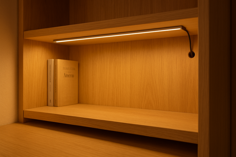
| Hiding the feed wire8 | Drill Through. The cleanest method is to drill a small hole directly behind where the LED strip will end, feeding the wire through the surface (e.g., the back of a cabinet or a bookshelf). | Power Drill, Small Drill Bits (e.g., 1/8"), Low-Profile Wire (22AWG or 20AWG). | Drill the hole before you mount the strip or channel. Solder the wire to the strip, feed the wire through the hole, and then mount the strip. This creates a completely seamless wire entry point. |
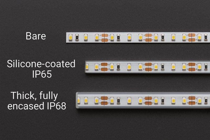
| Containing the strip and wires | Aluminum Channels9. Use a slim aluminum channel. The channel not only diffuses the light and acts as a heat sink but also provides a neat housing to hide the strip and the soldered connection point. | Aluminum Channels, Diffuser Covers, Mounting Clips. | For a truly clean look, use recessed channels. This requires routing a groove into the wood or substrate, allowing the channel to sit perfectly flush with the surface. The result is a light source that appears to be part of the material itself. |
| Connecting multiple shelves | Vertical Wire Channel10. To power shelves in a vertical stack (like a bookshelf), you can run a single, heavier gauge wire down the back corner and tap into it for each shelf with smaller wires. | WireMold or other surface-mount raceway, Adhesive, Staple Gun. | If you can’t go behind the material, hide the vertical wire run in a corner where it’s least visible. You can even use a small, paintable wire channel (raceway) to blend it into the background. |
| Low-profile connections | Direct Soldering11. In extremely tight spaces, solder your feed wires directly to the strip’s pads. Solderless connectors are often too bulky to fit in slim channels or tight corners. | Soldering Iron, Fine-gauge Solder, "Helping Hands" tool. | Use minimal solder to create a strong but small joint. Cover the connection with a piece of polyimide (Kapton) tape instead of bulky heat-shrink tubing for insulation in very tight spaces. |
Conclusion
Mastering installations in corners and difficult spaces is a skill. It requires planning, using the right techniques like soldered jumpers, and choosing the right product for the specific challenge, like a flexible strip for curves.
-
Understanding the moment of truth can elevate your lighting installation skills and ensure a professional finish. ↩
-
Discover why this common shortcut can lead to failures and how to avoid it for a professional outcome. ↩
-
Explore the advantages and disadvantages of solderless connectors to make informed decisions for your projects. ↩
-
Learn the best practices for using soldered wire jumpers to achieve reliable and aesthetically pleasing lighting corners. ↩
-
Explore this link to discover various LED strip types and their ideal uses, enhancing your lighting projects. ↩
-
Learn about the unique features of S-Type LED strips and how they can enhance your designs with flexibility. ↩
-
Find out how Side-Emitting LED strips can create stunning neon-like effects in your projects. ↩
-
Explore effective techniques for concealing feed wires to achieve a seamless lighting design. ↩
-
Learn how aluminum channels enhance aesthetics and functionality in lighting setups. ↩
-
Discover the benefits of vertical wire channels for organizing and concealing wiring in multi-shelf setups. ↩
-
Find out why direct soldering is crucial for compact installations and how it ensures reliability. ↩