Your LED strip installation looks great at first, but soon it starts to flicker, dim at the end, or fail completely. You’re facing a costly callback, an unhappy client, and a damaged reputation.
A flawless installation requires a systematic wiring approach: correctly calculating power supply wattage, ensuring secure connections, planning for voltage drop on long runs, and properly integrating controllers for dimming and color control.
I’ll never forget a call I got from a contractor who was in a total panic. He had installed hundreds of feet of our LED strips in a new restaurant. Two days before the grand opening, half the lights were flickering, and the long runs in the ceiling coves were bright orange at the start and a dull, dim red at the end. He thought the product was defective. I got on a video call with him from the job site. The problem wasn’t the strips; it was the wiring. He was using severely underpowered drivers and running single 50-foot lengths from one power source. He had created a massive voltage drop problem. We worked out a solution with him, which involved new drivers and a parallel wiring plan, but it was a stressful, expensive lesson for him to learn. This manual is designed to prevent you from ever having to make that call.
How Do You Choose the Right Power Supply?
You’ve chosen the perfect LED strip, but you’re unsure what power supply to use. You make a guess, and the system either doesn’t turn on, or it overheats and fails prematurely, creating a serious fire hazard.
Calculate the total wattage of your LED strip run (Watts per Foot x Total Feet), then add a 20% safety margin. Choose a power supply (driver) with a wattage rating that meets or exceeds this total. Finally, ensure the voltage matches exactly (12V or 24V).
I was working with a client, Tom, a skilled project manager who was new to specifying low-voltage lighting. He had a project for retail display cases, about 10 feet of strip per case. He calculated the wattage perfectly but bought a power supply with that exact wattage rating. He didn’t add the 20% headroom. The installation worked, but a month later, two of the fifty power supplies had failed. He was frustrated. I explained that a power supply running at 100% of its capacity is like a car engine constantly running at the redline. It will work for a while, but it’s under extreme stress and will fail much sooner. The 20% rule isn’t just a suggestion; it’s the professional standard for building a reliable, long-lasting system and preventing premature failure. It’s a simple step that saves you from future headaches.
The Power Calculation Blueprint
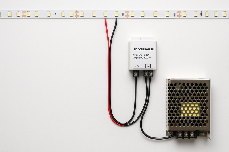
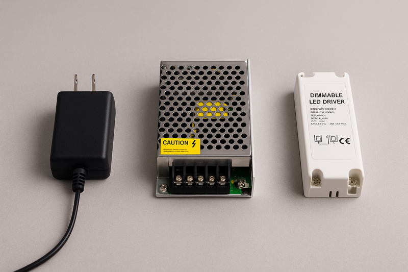
The power supply, or LED driver, is the heart of your lighting system. Getting this component right is non-negotiable for safety, reliability, and performance. Choosing an undersized driver will cause flickering and failure. Choosing an oversized one is a waste of money. The process is simple math, but it’s the most critical calculation you will make in the entire installation. For a professional like Tom, being able to confidently and correctly spec the power supply for any size job is a fundamental skill. It also requires understanding the different types of drivers available and which ones are appropriate for a given application, especially when it comes to meeting building codes and certification requirements.
| Step | Action | Example Calculation | Jermey’s Pro Tip (Your Expertise) |
|---|---|---|---|
| 1. Find the Strip’s Wattage | Look at the product spec sheet for the "Watts per Meter" or "Watts per Foot1." We provide this for all Rhlite products. Let’s say our strip is 4.5 Watts/Foot. | Product: Rhlite Pro-Series 3000K Strip. Specification: 4.5 W/ft. | If a spec sheet only gives Watts per 5m Reel, don’t guess. Do the math. A 24W reel is 24W / 16.4ft = 1.46 W/ft. Don’t let a lazy spec sheet cause you to make a critical error. |
| 2. Calculate Total Run Wattage | Multiply the Watts per Foot by the total length of the strip you plan to power with a single driver. Let’s say we have a 20-foot run. | 4.5 W/ft * 20 ft = 90 Watts. This is the total power the strip will draw. | Always measure your final installed length. Don’t just estimate. If the client makes a last-minute change and adds two feet to the run, you must recalculate. |
| 3. Apply the 20% Safety Headroom2 | Multiply the total run wattage by 1.2. This ensures the driver is not running at 100% capacity, which improves longevity and safety. This is the most crucial step. | 90 Watts * 1.2 = 108 Watts. This is your minimum required power supply wattage. | This is called the "80% rule" in the electrical world. Never load a circuit to more than 80% of its rated capacity. This isn’t just a best practice for LEDs; it’s a core principle of safe electrical design. |
| 4. Select the Power Supply & Match Voltage | Choose a commercially available power supply with a wattage rating at or above your calculated minimum. The most common size up from 108W is likely 120W or 150W. Crucially, the voltage must match. If you have a 24V strip, you must use a 24V driver. | We need a 24V driver rated for at least 108W. We select a 24V, 150W UL-Listed driver3. | UL Listing is key. For professional jobs in North America, using a UL-Listed (or equivalent) driver is often required by code. It ensures the product has been tested for safety. We supply Class 2 drivers, which have inherent power limitations that offer additional safety benefits. |
What’s the Best Way to Cut and Connect Strips?
You’re using cheap, clamp-style connectors. The connection seems fine at first, but then it becomes intermittent. The lights flicker when touched, or a section goes dead, forcing you to troubleshoot on-site.
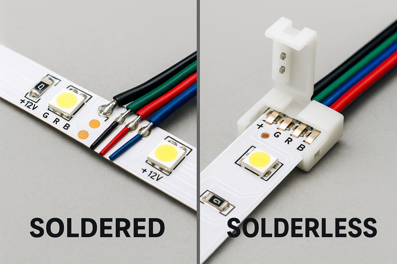
Soldering provides the most reliable, permanent, and electrically sound connection. For situations where soldering isn’t feasible, use high-quality, professional-grade connectors that securely pierce the contact pads, not just create pressure.
A contractor installing lighting in some museum display cases called me, frustrated. He was using solderless connectors to join the sharp corners, and some of them were failing. These were priceless artifacts; they couldn’t risk a light failing. I asked him to send me a photo of the connector. It was a cheap, clear plastic "clamp" style he bought online. I explained that those rely on a tiny bit of metal pressing against the copper pad. Over time, with vibrations and temperature changes, that connection loosens. I overnighted him some of our professional-grade connectors and a sample of a soldered joint. The next day he called back. "I get it now," he said. He had his lead installer solder every joint from then on. Soldering is a skill, but it’s a skill that guarantees reliability.
The Art of the Connection
The connection points are the weakest links in any LED strip installation. A poor connection creates electrical resistance4, which leads to heat, flickering, and eventual failure. While solderless connectors5 offer speed, a professional must understand the trade-off they are making. For a long-lasting, commercial-grade installation6 that you can warranty with confidence, soldering7 is the gold standard. However, high-quality solderless connectors have their place, especially in tight spots or for rapid prototyping. The key is to know when and how to use each method correctly, and to never, ever compromise on the quality of the connector itself. This is a detail that separates a high-end installer from the competition.
| Method | Description | Pros | Cons | Jermey’s Professional Best Practices |
|---|---|---|---|---|
| Soldering | The process of melting a metal alloy (solder) to create a permanent, conductive bond between the wires and the copper pads on the LED strip. | Most Reliable: Creates a permanent, vibration-proof electrical and mechanical bond. Lowest Profile: A clean solder joint is much smaller than any connector. Best Conductivity: Minimal resistance means less heat buildup and no voltage loss at the joint. | Requires Skill & Tools: Needs a soldering iron, solder, and some practice to master. Time-Consuming: Slower than using a connector, especially on a large job. Difficult in the Field: Can be challenging to do up on a ladder or in a tight space. | 1. Pre-tin both surfaces: Apply a small amount of solder to the copper pads on the strip and to the stripped ends of your wires first. 2. Use Flux: A small dab of flux paste on the pads helps the solder flow cleanly and form a strong bond. 3. Quick & Clean: Use a temperature-controlled iron (around 350°C / 660°F). The goal is to heat the pad and wire, let the solder flow, and get out quickly—less than 3 seconds to avoid damaging the LED. |
| Solderless Connectors (Professional Grade) | These are small plastic housings that either clamp onto the strip or have sharp pins that pierce through the flexible PCB to make contact with the copper pads. | Fast & Easy: No special tools or skills required. Excellent for rapid installation. Reversible: You can easily disconnect and re-connect if you make a mistake. Good for Tight Corners: Specialized L-shape connectors make clean 90-degree turns. | Variable Reliability: The quality varies massively between brands. Cheap connectors are the cause of failure. Bulky: They are much larger than a soldered joint and may not fit in slim channels. Not for High-Current Strips: Can overheat on high-power strips. | Look for "insulation-piercing" designs. These are superior to simple "pressure" clamps. Check polarity: Always match the + and – markings on the strip to the wire colors. Secure the Connection: After clamping the connector shut, give the wires a gentle tug to ensure they are secure. For extra security, wrap the connector with electrical tape or use heat-shrink tubing. Buy from your strip supplier: We offer connectors that are specifically tested and matched to the thickness and pad size of our strips. |
How Do You Prevent Voltage Drop in Long Runs?
You’ve installed a long, 30-foot run of LED strips in a ceiling cove. You turn it on, and the start of the strip is bright and the correct color, but the end is noticeably dimmer and sometimes has a reddish tint.
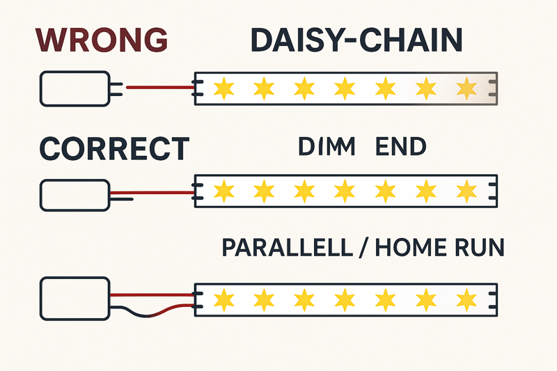
Never run more than the recommended maximum length (typically 16-32 ft) in a single series. For longer runs, you must run parallel wires from the power supply to the start of each new section (a "home run") or power the strip from both ends.
I was on-site at a high-end home theater build. The designer wanted a perfectly seamless glow around a massive ceiling feature that was over 60 feet in circumference. The electrical contractor, a very experienced guy but new to low-voltage LEDs, planned to just connect four reels of our strips end-to-end and power it from one spot. I had to intervene. I drew a diagram on a piece of drywall for him, showing a "star" wiring pattern. We would place the driver in the center and run four separate "home run" wires from the driver to the start of each 16-foot section. It meant using more wire, but it guaranteed that every single section received the full 24 volts. The result was a perfectly uniform, flawless ring of light. He understood immediately: with low voltage, the wiring strategy is just as important as the light itself.
The Physics of a Perfect Glow
Voltage drop8 is the gradual loss of voltage along the length of a conductor. All wires have some resistance. In low-voltage systems (like 12V or 24V DC), even a small loss of voltage has a big impact on the brightness and color of the LEDs at the end of the run. This is not a product defect; it’s a law of physics. A professional installer must understand and plan for it. Ignoring voltage drop is the most common mistake that separates amateur work from professional results. Using a 24V system helps, as it suffers from less voltage drop than a 12V system over the same distance, but even 24V strips have their limits. The key is to design a wiring layout that ensures every part of the strip receives the voltage it needs to perform correctly.
| Wiring Method | Description | When to Use It | Jeremy’s Best Practice Advice |
|---|---|---|---|
| Single End Feed (Standard) | A single run of LED strip is powered from one end. | For any run up to the manufacturer’s recommended maximum length (e.g., one 16.4 ft / 5m reel). | This is the standard, simple method for most applications. Our 24V Pro-Series strips can often be run up to 10m / 32ft in a single feed due to their thicker copper PCB, but always check the spec sheet. |
| Center Feed / Both Ends Feed9 | For a single, continuous strip that is longer than the max recommended length, you can power it from the center, with the current flowing outwards in both directions. Alternatively, you can power it from both ends with wires running back to the same driver. | For a single continuous run that is up to double the standard max length (e.g., creating a 30ft run from two 15ft sections). | This is a clever trick to double your run length without a visible break. The key is to ensure both connections are solid. Electrically, this is the same as two separate runs. |
| Parallel "Home Runs"10 | For very long installations (like large room coves), multiple separate strips are used. Each strip (or section) is wired directly back to the power supply using its own set of wires. | This is the only professional method for installations longer than about 30-40 feet. It is the gold standard for large-scale projects. | Use a terminal block or bus bar near the power supply to create a clean junction point for all your home run wires. Use the correct gauge wire. For longer home runs, you may need to use thicker wire (e.g., 16AWG or 14AWG) to avoid voltage drop in the wires themselves! Calculate this based on your load and distance. |
Conclusion
Professional LED strip wiring is a system. It requires choosing the right power supply, making reliable connections, and designing a layout that defeats voltage drop for perfectly uniform results every time.
Understanding Watts per Foot is crucial for selecting the right LED driver and ensuring optimal performance. ↩
Exploring the importance of 20% Safety Headroom can enhance your knowledge of safe electrical practices and longevity of devices. ↩
Learn about UL-Listed drivers to ensure safety and compliance in your electrical installations. ↩
Understanding electrical resistance can help you avoid common pitfalls in LED installations. ↩
Learn about solderless connectors and their applications for quick and efficient LED installations. ↩
Discover the standards and practices that elevate LED installations to commercial-grade quality. ↩
Explore the advantages of soldering for reliable LED connections, ensuring durability and performance. ↩
Understanding voltage drop is crucial for ensuring optimal LED performance and avoiding common installation mistakes. ↩
Learn about the center feed method to maximize the length of your LED runs without compromising on brightness. ↩
Discover why parallel home runs are the gold standard for long LED installations and how to implement them effectively. ↩